
Tutorials
Introduction
The following tutorials use the Development Board. Some also make use of an Arduino Uno R3. The MULTOS workspace can be downloaded from here. It also contains the necessary Arduino sketches for each project. The source code is fully commented and provides the main guidance for these tutorials. Note: you will need to edit the COM port number in all the batch files to match that on your computer.
At various stages you maybe prompted to switch the Development Board between Command Mode and Embedded Mode. To do this:-
-
- Turn off the MULTOS chip (switch S2 in the down position)
- Fit (command mode) or remove (embedded mode) the jumper JP5
- Turn the MULTOS chip back on (switch S1 in the up position)
Jump to the following tutorials: LED Flash | Timed Blink | Hello World | I2C Master | I2C Slave | SPI Master | Sending APDUs in Command Mode | Two Serial Ports | Abend / Fault Handling | Wifi | Application Updating
LED Flash
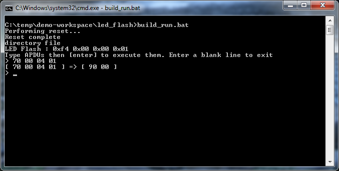
Runs in COMMAND MODE. This application will flash the on-board LED. The number of times to flash is given in the command P1 parameter and the gap between flashes (in seconds) by the P2 parameter. The structure of an APDU is described in the MULTOS Developers Guide in section 3.
This example can be run through the debugger in Eclipse or by using the batch file build_run.bat as shown below.
Timed Blink
This introduces the concept of running a MULTOS Trust Anchor in Embedded Mode. Each application loaded to the device registers the events it is interested in and provides the code required to handle those events. On receipt of an event, MULTOS calls the applications that have registered an interest in that event (they are called in the order they were loaded to the device). In this example, a timer event is used to blink an LED.
To load the application, ensure that the Development Board is in Command Mode and run the loader.bat script. Once loaded, switch to Embedded Mode – the application will start to run as soon as the power is switched back on.
Note: The code for the tutorial includes commented out lines for switching the chip in and out of embedded low power mode. It is useful to put the chip into low power mode to save energy when the device is waiting for an event to happen (including timer events). Care must be taken, however, as this setting applies to the whole chip and all embedded applications running on it.
Hello World
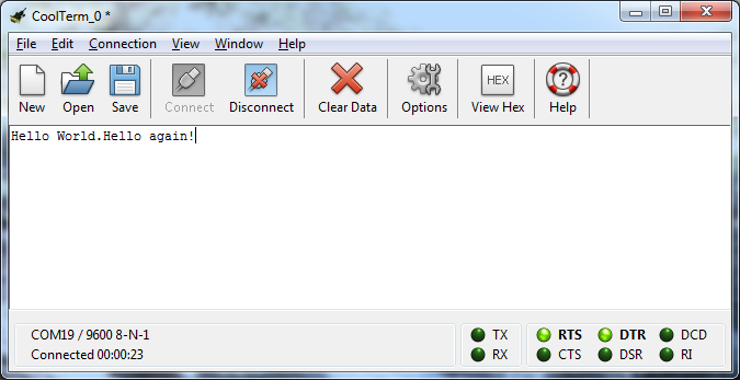
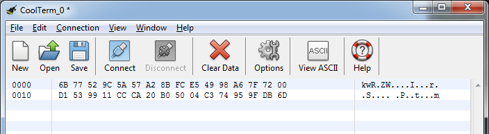
This application can be loaded alongside the Timed Blink application, demonstrating how more than one application can be registered to respond to events in Embedded Mode. This application introduces using the default serial port in an application and the handling of GPIO events. You will need a tool to read the serial port such as CoolTerm.
As before, to load the application, ensure that the Development Board is in Command Mode and run the loader.bat script. This time the script does not delete existing applications from the device. If you need to delete an existing application there are two basic options:-
- Erase all applications: hterm -serial COMx -cardtype MI-M5 -clean
- Erase an application using its AID e.g.: hterm -serial COMx -cardtype MI-M5 -deleteaid F4000001
Once loaded, switch to Embedded Mode – the application (and Timed Blink if still loaded) will start to run as soon as the power is switched back on. The LED will blink (Timed Blink application) and when the white push button on the Development Board is pressed, the messages “Hello World” and “Hello again!” will be sent over the serial port.
Note: The code for the tutorial includes commented out lines for switching the chip in and out of embedded ultra low power mode. It is useful to put the chip into this mode to save energy when the device is waiting for an event to happen (the chip’s timers are stopped in this mode, so the wake up events must be related to I/O). Care must be taken, however, as this setting applies to the whole chip and all embedded applications running on it.
I2C Master
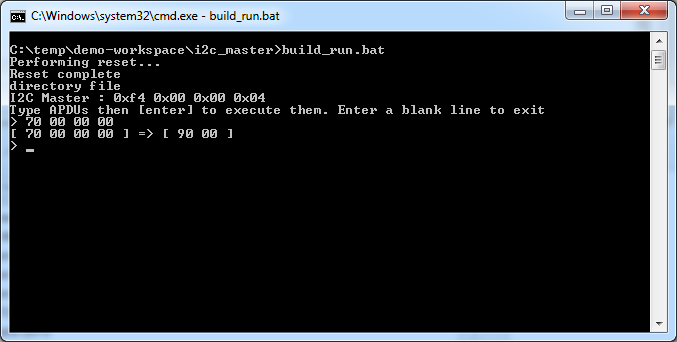
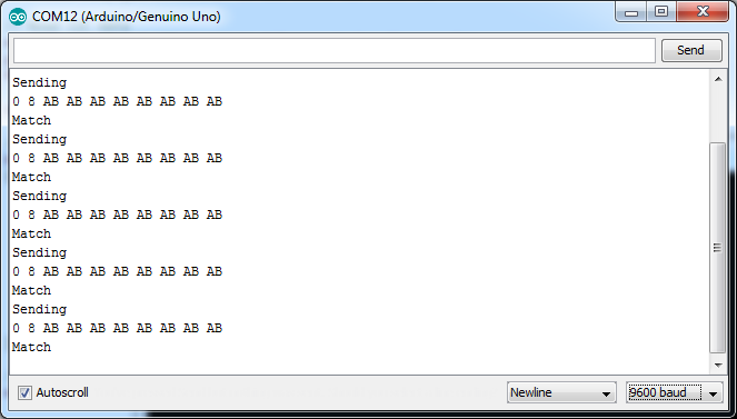
In this application, a MULTOS application (running in command mode) writes random data to an Arduino slave over I2C, the Arduino copies the received data to different registers which MULTOS then reads back. It compares the values to those originally sent and if they match, 0x9000 is returned, if they don’t match 0x9001 is returned.
- The Arduino SCL pin needs to be connected to pin G8 on the Development Board
- Connect Arduino SDA pin to pin G9.
- Connect any Arduino GND pin to any Dev. Board GND pin.
Please note: Depending on the Arduino model used, it may need to be powered separately. The Vcc out connection from the MULTOS Development board is 3.3V.
The MULTOS application can be run through Eclipse or from the batch file build_run.bat.
I2C Slave
This demonstrates using high level I2C calls to talk to an Arduino with the Arduino as the master. The following connections are required:-
- The Arduino SCL pin needs to be connected to pin G8 on the Development Board
- Arduino SDA pin to pin G9.
- Any Arduino GND pin to any Dev. Board GND pin.
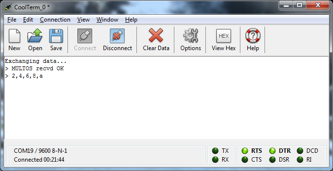
To run, load the MULTOS application first (in Command Mode) using loader.bat then switch to Embedded mode. Once the Arduino application is loaded messages will start to be exchanged between the two devices. Both output information on their serial ports that can be viewed.
SPI Master
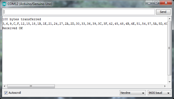
This tutorial brings together a number of features already introduced and adds in use of SPI peripherals with MULTOS. In this demo, MULTOS waits for the push button on the development board to be pressed then exchanges a message with the Arduino slave. Both MULTOS and the Arduino validate the messages received and output messages on their respective serial ports.
MULTOS is running in Embedded Mode and as with other Embedded Mode tutorials, needs to be loaded in Command Mode using the loader.bat file.
The boards need to be connected as follows:-
- MOSI: MULTOS G0 to Arduino 11
- MISO: MULTOS G1 to Arduino 12
- CLK: MULTOS G2 to Arduino 13
- SS: MULTOS G3 to Arduino 10
- GND: Any MULTOS GND pin to any Arduino GND
Sending APDUs in Command Mode over Serial
Firstly, connect the MULTOS Dev. Board and Arduino together as follows:-
- GND: Any MULTOS GND pin to any Arduino GND
- TX/RX: Arduino pin 3 to MULTOS RXA pin
- RX/TX: Arduino pin 2 to MULTOS TXA pin
In this example, the “LED Flash” application will be needed again the MULTOS device. Please load it in Command Mode using the build_run.bat file in the project. This time however, just hit return at the prompt to exit hterm.
Then move the slider switch S1 from the “USB” to “RXA/TXA” position. This re-routes the serial pins to the Dev. board edge connector rather than the USB/Serial interface chip.
Instead of APDUs being sent to MULTOS from hterm, APDUs will be sent to it from an Arduino. The example Arduino code in the apdu_sender sketch shows how to build up the necessary command frame and handle the response (details of the protocol are here). Load the sketch. When it starts, it will send APDUs to MULTOS causing the LED to flash on and off. The Arduino sketch will send messages out on the serial monitor window.
Important: After running this example, remember to set slider switch S1 back to the “USB” position.
Two Serial Ports
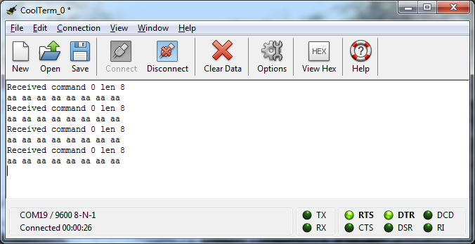
This demonstrates how two serial ports can be set up and used. Random hexadecimal numbers are generated by the Arduino, transmitted to the secondary serial port on the MULTOS Trust Anchor and relayed through the primary serial port back to the PC where they can be viewed.
Note: Start with the Arduino powered off.
The required connections are:-
- GND: Any MULTOS GND pin to any Arduino GND
- RX/TX: Arduino pin 2 to MULTOS G1
- TX/RX: Arduino pin3 to MULTOS G0
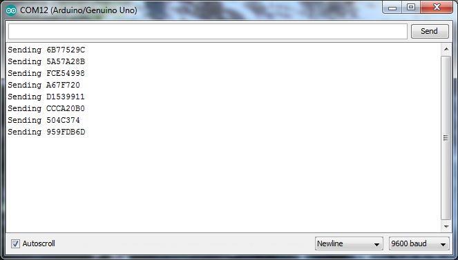
First load the MULTOS application in Command Mode using the loader.bat script and then switch to Embedded mode. MULTOS is now listening. Then connect the Arduino and upload the sketch. It will immediately start sending out a random message every five seconds. You should see output like this.
Abend / Fault Handling
“Abend” means “abnormal end” and refers to the situation where the MULTOS operating system has detected an invalid instruction or memory access attempt and stops executing. This is a security mechanism and in a smartcard forces the card to be reset or be re-inserted into the reader so that the power is cycled.
In an embedded device, having the device just stop may be problematic. To allow the device to cleanly handle such faults, a handler function can be specified using the function miSetAbendFunction() as follows:-
void abendFnc(void)
{
    BYTE bCode;

    // You can find out the cause of the fault
    bCode = miAbendReason();

    // And take action depending on what has happened. For example
    if( bCode == MI_ABEND_REASON_PERIPHERAL_NO_PERMISSION )
        miPerformHalt(); // Device stops running until reset or restarted.

    else if (bCode == MI_ABEND_REASON_FIREWALL_VIOLATION )
        miPerformReset(); // Device is restarted

    // Otherwise return control to MULTOS. If in Command Mode, information can be returned.
    // For example, the status word could provide some information on the fault
    SW1 = 0x6A;
    SW2 = bCode;
    multosExit();
}

void main(void)
{
    miSetAbendFunction((WORD)abendFnc);

    // Application code follows....
}
Wifi
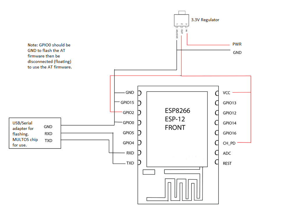
This example code is somewhat more involved than those above and requires a deal more setup. Its purpose is to show how you can make use of an ESP8266 WiFi module to allow a MULTOS Trust Anchor to communicate directly via WiFi. The workspace can be downloaded here. There are many variants of the ESP8266. Here we use an ESP-12 module.
The basic approach here is to make use of the AT command set that is available for the ESP8266. The workspace contains three projects (build in this order):-
- libwifi : The API to use in applications for calling the WiFi driver. It includes basic functions for establishing connections, sending HTTP GET requests and publishing messages to an MQTT queue. wifi.h includes details of the AT firmware needed.
- esp_wifi_app: The MULTOS driver for the ESP8266. This interfaces to the ESP8266 over a serial port, building the necessary AT command frames and decoding the replies.
- wifi_testbed: A sample embedded-mode application that makes use of libwifi. Note: you will need to change this code to add in your own connection and MQTT details.
The ESP8266 AT Commands reference document is here. Please refer to it for details on how to load the firmware.
The ESP12 is wired as follows (note the use of a separate power supply. The ESP8266, when active, consumes more power than the MULTOS Developer Board can supply).
Application Updating
This tutorial shows how the code for a MULTOS application can be updated whilst preserving some or all of the application’s data. There are two versions of the same (command mode) application in the workspace: counterv1 and counterv2. They have several important properties:-
- The have the same Application ID (AID)
- The access_list includes the “Allow Application Reload” bit ( xx1x xxxx xxxx xxxx )
- Version 2 has the “Process Events” permission set in the access_list ( xxxx x1xx xxxx xxxx )
Each time counterv1 is executed, it increments a counter stored in static memory. After loading counterv2 (without deleting counterv1 first) MULTOS executes counterv2 with the EVENT_CREATE flag set. This gives counterv2 the opportunity to copy data from counterv1 before counterv1 is deleted.
To see this in action execute the build_run_v1.bat script which loads counterv1 and runs it three times to increment the counter. Then run build_run_v2.bat which upgrades the application and executes it three more times. The counter output by the updated application should continue from where version 1 left off.
If the original application does not include the “Allow Application Reload” bit in the access_list, it can still be replaced by a new version of the application but the new version will not have access to the memory of the original.
If the new version of the application does not specify the “Allow Application Reload” bit in the access_list, then the old application will have to be deleted first (as normal) before loading the new application.
IMPORTANT: multosCopyStaticFromReplacedApp() only works with SmartDeck 3.2.0.4 or later.