
Development Board Details | Breakout Board Details | Trust Core Details | Contactless Board Details
Nano Board Details
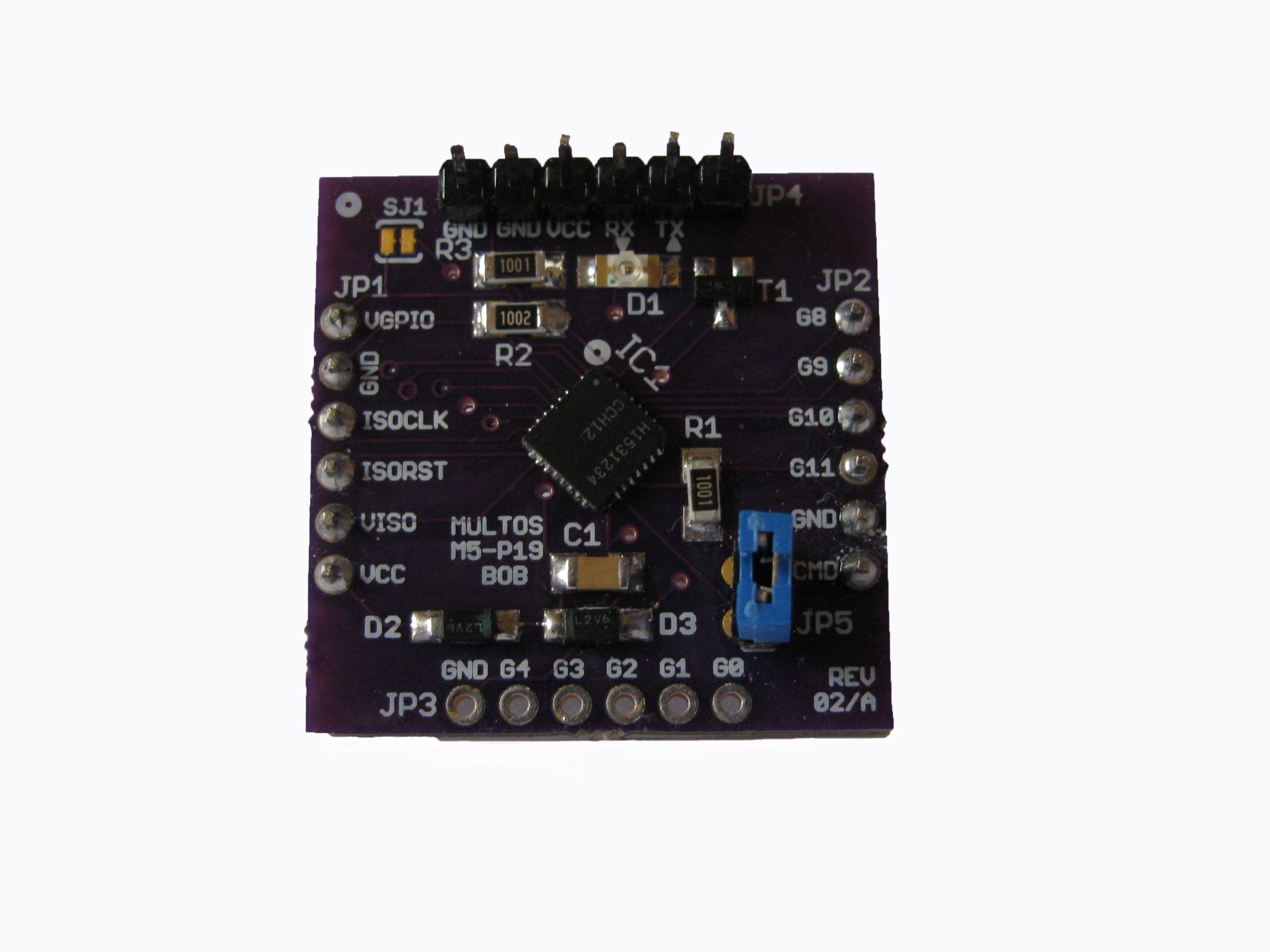
The board has five sets of headers labelled JP1 to JP5. Header pins are supplied but not fitted giving the user flexibility.
- JP1: Smartcard ISO7816 interface (except for CMD which is on JP2).
- Rev2/A boards: SJ1 is an isolation jumper which can be cut to isolate VCC from VGPIO. Important Note: VISO needs to be connected to VGPIO if using Command Mode.
- Rev3 boards: Normally only VCC needs to be connected. However if separate supplies are wanted for the GPIO and ISO circuits (VGPIO and VISO) then SJ1 and SJ2 should be cut.
- JP2: mixed use pins
- G8: GPIO8 or SCL
- G9: GPIO9 or SDA
- G10: GPIO10 or TX
- G11: GPIO11 or RX
- CMD: ISO_IO or Command Mode selection.
- JP3: GPIO pins
- JP4: FTDI Basic header connection. Replicates connections on JP1, JP2 and JP3 but in a convenient layout for connecting to FTDI USB-Serial devices.
- JP5: When closed the device operates in Command Mode, when open in Embedded or Smartcard Mode.
D1: This is an LED connected to GPIO6