
Development Board Details | Trust Core Details | Contactless Board Details | Nano Board Details
Breakout Board Details
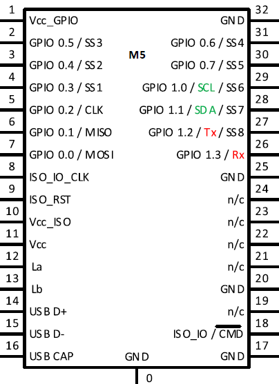
The Breakout board makes all 32 pins of the M5 chip’s QFN32 package available in a DIP-32 format. This page provides details of the chip and its pin-out.
M5 Features
| Feature | Description |
|---|---|
| Secure Operating System | MULTOS 4.5.1 (M5-P19) MULTOS 4.5.3 (M5-P22) |
| Secure Microcontroller | Infineon SLE78CLUFX5000PHM |
| RAM | 9,900 bytes available to applications + 3,200 bytes of public RAM |
| NVM | At least 250Kb availabe for applications Note: The maxiumum amount of normally addressable static memory per application is 32Kb. Use AdditionalStatic primitives or delegation if more memory is needed. |
| NVM page size | 256 bytes |
| Crypto co-processors | Crypt@2304T (asymmetric), SCP (symmetric), HASH |
| Timers | 4 |
| Watchdogs | 2 |
| Random number generators | PRNG, TRNG |
| CRC | 16 bit |
| UART | Hardware UART designed to support ISO 7816-3 smartcards. Software UART support available in MULTOS. |
| RF interface | ISO/IEC 14443 type A and B, ISO/IEC 18092 passive mode, Mifare-compatible functionality, DCLB |
| I2C | Master and slave modes. Supports clock stretching in slave mode |
| SPI | Master mode |
| GPIO | Up to 12 GPIO pins |
| Internal clock | Up to 50MHz |
| Low-power sleep mode | |
| CPU | Based on the MCS 251 instruction set, Dual CPU, 1K cache |
| Security sensors | Temperature, Light, Voltage, Frequency, I2 shield |
| Package | VQFN-32-13 |
Maximum Ratings
| Parameter | Minimum | Maximum |
|---|---|---|
| Vcc | -0.3V | 7.0V |
| Vcc_ISO | -0.3V | 7.0V |
| Vcc_GPIO | -0.3V | 7.0V |
| ISO_0, ISO_1, ISO_2 | -0.3V | Vcc_ISO + 0.3V |
| GPIO0.0-GPIO1.3 | -0.3V | Vcc_GPIO + 0.3V |
Nominal Ratings
| Parameter | Minimum | Maximum |
|---|---|---|
| Vcc | 1.62V | 5.5V |
| Vcc_ISO | 1.62V | 5.5V |
| Vcc_GPIO | 1.62V | 5.5V |
Current Consumption
The following typical figures are for running in Embedded Mode (supply 5V) with no application executing (i.e. device is idling waiting for an event):-
- Low power mode NOT enabled: 10mA
- Low power mode enabled: 3mA (Hardware sleep mode)
- Ultra low power mode: 50uA (+timers disabled)
Pinout
| Pin | Symbol | Direction | Pad Type | Pad Power Supply | Signal Function/Remarks |
|---|---|---|---|---|---|
| 1 | Vcc_GPIO | n/a | Power supply | n/a | Pad supply Vcc_GPIO |
| Each group of GPIO pins (G0-G3, G4-G7, G8-G11) can supply a maximum of 4mA at 5V. | |||||
| 2 | GPIO0.5 (G5) | I/O | GPIO_IO / SS3 | Vcc_GPIO | GPIO or SPI Slave Select 3 when configured by application. |
| 3 | GPIO0.4 (G4) | I/O | GPIO_IO / SS2 | Vcc_GPIO | GPIO or SPI Slave Select 2 when configured by application |
| 4 | GPIO0.3 (G3) | I/O | GPIO_IO / SS1 | Vcc_GPIO | GPIO or SPI Slave Select 1 when configured by application |
| 5 | GPIO0.2 (G2) | I/O | GPIO_IO / CLK | Vcc_GPIO | GPIO or SPI clock when configured by application |
| 6 | GPIO0.1 (G1) | I/O | GPIO_IO / MISO | Vcc_GPIO | GPIO or SPI MISO when configured by application |
| 7 | GPIO0.0 (G0) | I/O | GPIO_IO / MOSI | Vcc_GPIO | GPIO or SPI MOSI when configured by application |
| 8 | ISO_1 | I/O | ISO_IO_CLK | Vcc_ISO | 7816-3 card usage: UART_CLK, 7816-3 terminal usage: TUART_CLK, DCLM usage: DCLB_CLK |
| 9 | ISO_2 | I/O | ISO_RST / Reset | Vcc_ISO | 7816-3 card usage: UART_RST, 7816-3 terminal usage: TUART_RST, DCLM usage: DCLB_RST or Pull low to reset device when not using the smartcard interface.* |
| 10 | Vcc_ISO | n/a | Power supply | n/a | Pad supply Vcc_ISO |
| 11 | Vcc | n/a | Power supply | n/a | Power supply Vcc |
| 12 | La | I/O | Contactless | n/a | Coil connection La |
| 13 | Lb | I/O | Contactless | n/a | Coil connection Lb |
| 14 | D+ | I/O | USB_IO | Vcc | USB signal D+ (use not supported) |
| 15 | D- | I/O | USB_IO | Vcc | USB signal D- (use not supported) |
| 16 | USBCAP | n/a | Power supply | n/a | An external buffer capacitor of 100nF must be connected to GND for standard USB operation (use not supported) |
| 17 | GND | n/a | Power supply | n/a | GND |
| 18 | ISO_0 | I/O | ISO_IO / Command Mode | Vcc_ISO | 7816-3 card usage: UART_IO, 7816-3 terminal usage: TUART_IO, DCLM usage: DCLB_IO or When not using the smartcard interface the state of this pin is checked at power-up or on reset as follows:
|
| 19 | Reserved | ||||
| 20 | GND | n/a | Power supply | n/a | GND |
| 21 | Reserved | ||||
| 22 | Reserved | ||||
| 23 | Reserved | ||||
| 24 | Reserved | ||||
| 25 | GND | n/a | Power supply | n/a | GND |
| 26 | GPIO1.3 (G11) | I/O | GPIO_IO / Rx | Vcc_GPIO | GPIO or Serial Rx when in Command Mode (over serial interface) |
| 27 | GPIO1.2 (G10) | I/O | GPIO_IO / Tx / SS8 | Vcc_GPIO | GPIO or Serial Tx when in Command Mode (over serial interface) or SPI Slave Select 8 when configured by application |
| 28 | GPIO1.1 (G9) | I/O | GPIO_IO / SDA / SS7 | Vcc_GPIO | GPIO or I2C SDA when configured for use by application or in Command Mode (over I2C interface) or SPI Slave Select 7 when configured by application |
| 29 | GPIO1.0 (G8) | I/O | GPIO_IO / SCL / SS6 | Vcc_GPIO | GPIO or I2C SCL when configured for use by application or in Command Mode (over I2C interface) or SPI Slave Select 6 when configured by application |
| 30 | GPIO0.7 (G7) | I/O | GPIO_IO / SS5 | Vcc_GPIO | GPIO or SPI Slave Select 5 when configured by application |
| 31 | GPIO0.6 (G6) | I/O | GPIO_IO / SS4 | Vcc_GPIO | GPIO or SPI Slave Select 4 when configured by application |
| 32 | GND | n/a | Power supply | n/a | GND |
| Centre pad | GND | n/a | Power supply | n/a | GND |
* Note: Not supported on the M5-P19 found in a few very early prototype kits (pre. May 2018). The MULTOS version can be checked by using the command hterm -serial COMx -multos where x is the number of the serial port of your Development board. The rom_ic_details value will be 0x84 0x53 for M5-P22. The build number of the operating system can be obtained using the command hterm -serial COMx -apdu 80100A0006 .